

NewsDetails
Pipe Wall Thickness, Diameter and Pressure - A Practical Sizing Guide
author:Jinyuan time:2026-11-07 11:41:47 Click:182
Introduction
Most pipe specification errors come from mixing up nominal and actual dimensions. A 12 inch pipe is not 12 inches in diameter, a schedule 40 pipe does not always have the same wall as another schedule 40 pipe, and a wall thickness stated as a nominal value carries a manufacturing tolerance that reduces the minimum wall. Understanding these relationships prevents both over-design and unsafe under-design.
Outside Diameter and Nominal Size
Pipe is identified by nominal size, but the actual outside diameter is fixed by standard so that fittings, flanges and threads remain interchangeable. For NPS 12 and smaller, the outside diameter is larger than the nominal size; for NPS 14 and above, the outside diameter equals the nominal size in inches. ASME B36.10M lists the exact values, and those values should always be used in calculations rather than the nominal figure.
Schedule and Wall Thickness
Wall thickness is commonly expressed as a schedule number, such as Sch 20, Sch 40, Sch 80 or Sch 160. The schedule is not a fixed thickness; it is a designation that corresponds to a specific wall for each nominal size. Increasing the schedule increases the wall, but the same schedule number on a different diameter does not give the same thickness.
Schedule numbers were originally derived from a thickness series related to allowable stress, and for small sizes the higher schedules become progressively heavier. For large diameter line pipe, wall thickness is usually specified directly in millimetres, because schedule designations are not commonly used in transmission pipeline procurement.
Design Pressure Calculation
Internal pressure capacity is calculated from the pipe geometry and the allowable stress of the material. The Barlow relationship, expressed in the pipeline codes as a design factor equation, relates design pressure to twice the wall thickness, the allowable stress and the outside diameter. The design factor accounts for the consequence of failure and varies by location class and service medium.
The important consequence is that pressure capacity falls as diameter increases for a fixed wall. Doubling the diameter at the same wall thickness halves the pressure rating, which is why large diameter lines require proportionally heavier walls or higher grade steel to reach the same design pressure.
Wall Thickness Tolerance
Manufacturing standards permit the delivered wall to be thinner than nominal. For seamless pipe the tolerance is often expressed as a percentage, and for welded pipe it may be expressed as a percentage of nominal or as a combination of a percentage and an absolute value. The minimum wall, not the nominal wall, is what resists pressure and what should be checked against the design calculation.
For critical lines, the purchase order should specify minimum wall rather than nominal wall, so that the delivered pipe has the calculated resistance even at the thin end of the tolerance band.
Corrosion Allowance and Mill Tolerance
Where internal corrosion or erosion is expected, a corrosion allowance is added to the calculated wall. The allowance is a design decision based on expected service life and inspection frequency; it is not a substitute for internal lining or chemical treatment where those are needed.
Corrosion allowance must be added to the minimum required wall, and then the mill tolerance must be considered when setting the ordered nominal wall. Applying the allowance to the nominal wall and ignoring tolerance is a common error that quietly removes part of the safety margin.
Practical Selection Steps
Start with the design pressure and design temperature. Select the material and its allowable stress at temperature, then calculate the minimum wall using the applicable code and design factor. Add corrosion allowance, then convert to the ordered nominal wall by allowing for the mill tolerance. Finally check the result against handling, installation and buckling requirements, which often govern large diameter thin wall pipe.
For example, a low pressure water main may calculate to a wall that is impractical to handle, in which case the minimum practical wall governs and the pressure calculation merely confirms adequacy.
Conclusion
Wall thickness selection is a short calculation wrapped in a set of conventions. Use actual outside diameter, work from minimum wall rather than nominal, add corrosion allowance before applying tolerance, and check the outcome against installation loads. A specification that states diameter, grade, nominal wall, minimum wall, tolerance basis and standard removes most of the ambiguity that causes disputes at delivery.
References
[1] API Spec 5L: Specification for Line Pipe.
[2] ISO 3183:2019 Petroleum and natural gas industries – Steel pipe for pipeline transportation systems.
[3] ASME B36.10M: Welded and Seamless Wrought Steel Pipe.
[4] ASME B16.5: Pipe Flanges and Flanged Fittings, NPS 1/2 through NPS 24.
[5] ASME B16.9: Factory-Made Wrought Buttwelding Fittings.
[6] ISO 21809-1:2018 External coatings for buried or submerged pipelines – Polyolefin coatings (3PP and 3PE).
[7] EN 10204:2004 Metallic products – Types of inspection documents.
 Recommended Products
-
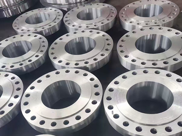
Carbon Steel Flanges for Pipe to Pipe Connections
-
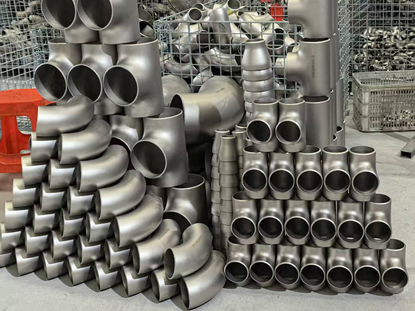
Carbon Steel Elbow in Bulk Supply for Plant Piping
-
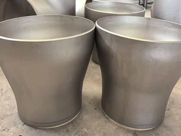
Large Diameter Concentric Reducer for Transmission
-
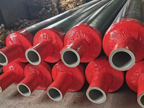
Polyurethane Foam Insulated Pipe with Protected Ends
-
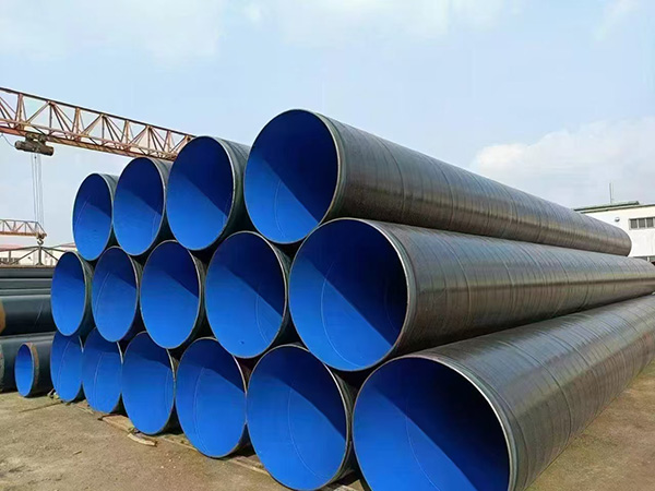
3PE Anti Corrosion Pipe with Internal Epoxy Lining
-
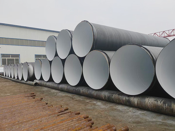
FBE Powder Coated Pipe for Underground Water Mains
Contact us
—— Contact:Manager
—— Tel:+86 18831780999
—— Email:960382820@qq.com
—— Url:https://www.jinyuanpipe.com
—— Address:Yanshan County Economic Development Zone, Cangzhou City, Hebei Province, China